


Framework objective and scope
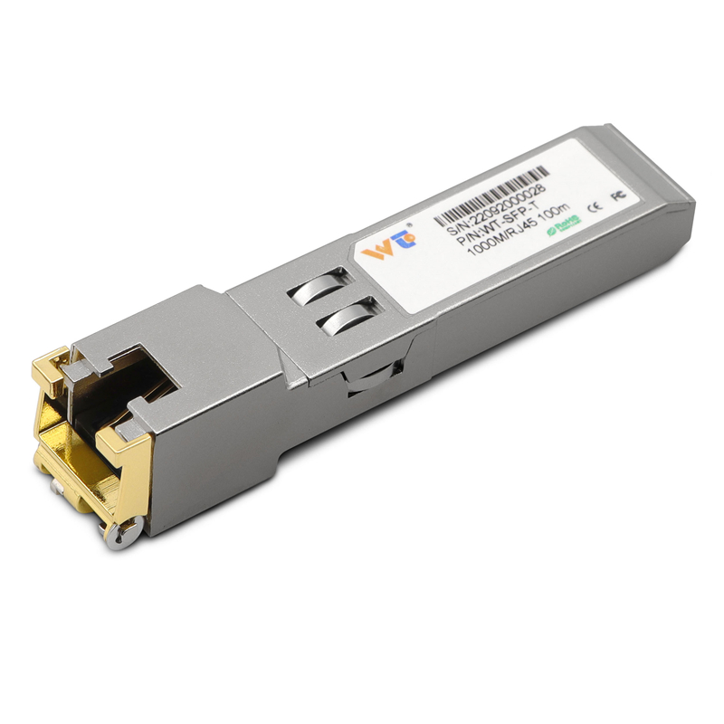
This is a practical framework for sizing and specifying power-supply redundancy on a four-port industrial switch used with short-reach copper modules. Start by mapping expected port modules — for example a mix of SFP+ ports using a sfp to rj45 transceiver and other copper transceivers — then layer uptime targets and service constraints. The goal is simple: ensure the switch stays operational through any single power fault while meeting thermal and maintenance constraints.
Operational context: where this matters
Industrial switches live in constrained enclosures: factory cabinets, rooftop shelters, and branch telecom closets. Real deployments show 10GBASE-T PHYs draw noticeably more power than SFP+ DAC links; industry measurements often place 10GBASE-T around 2–4 W per port versus sub‑1 W for direct-attach. Use that as a real-world anchor when building a power budget for tight spaces.
Step 1 — load profiling
Quantify steady and peak loads. Count active ports using a 10gbase t sfp+ copper transceiver or other modules, add CPU/ASIC consumption, and include PoE if present. Include transient currents (cold starts, link retrain, autonegotiation cycles). Document worst-case wattage per port and multiply by simultaneous-use probability to derive maximum operating draw.
Step 2 — redundancy topologies
Choose a topology that matches availability targets: N+1 battery-backed supply for minimal redundancy, dual hot-swap AC feeds for higher uptime, or fully isolated dual feeds with OR-ing diodes or an intelligent controller for seamless failover. For four ports, N+1 is often adequate but consider dual supplies when using multiple 10GBASE-T ports, since PHY heat and power raise failure risk.
Step 3 — thermal and enclosure constraints
Power implies heat. Confirm enclosure thermal capacity and airflow when adding redundant PSUs. A redundant PSU that doubles installed capacity can push a small cabinet past rated dissipation. Specify ambient limits and monitor inlet temperatures. If you plan hot-swap — it reduces downtime — verify that the board-level power sequencing handles live insertion without brownout on critical components.
Step 4 — maintainability and service model
Define who replaces failed supplies and how fast. Hot‑swappable modules with front access and LED fault indicators shorten MTTR. Keep spare parts matched to firmware and hardware revisions to avoid compatibility snags. Logically separate management and data-plane power so a PSU fault won’t take management access offline.
Common mistakes and mitigations
Three frequent errors: underestimating 10G port power, ignoring startup inrush, and assuming identical thermal behavior across vendor modules. Mitigations: run a 30–60 second startup test, include a 20–30% overhead on steady-state calculations, and test with the actual 10gbase t sfp+ copper transceiver models you plan to deploy. Use link aggregation and traffic shaping to avoid peak bursts that could trigger power excursions.
Selection checklist
Use this checklist before procurement:- Measured per-port power and peak startup current.- Redundancy topology: N+1, 1:1 dual-feed, or OR-ing controller.- Hot-swap capability and swappable fan trays.- Management-plane isolation and alarm support (SNMP traps, relay).- Environmental ratings (operating temp, vibration).

Integration notes for field teams
Document cabling and PSU feed routing to avoid single-point failures. Label AC circuits and maintain a log of firmware revisions tied to power-behavior fixes. When retrofitting 10G copper transceivers to older racks, reassess breaker sizing and panel loading; transformers and local PDUs may need upgrades for consistent redundancy.
Advisory — three critical evaluation metrics
1) Effective redundancy uptime: choose a topology that meets the required mean time between service interruptions (MTBSI) given measured PSU MTBF and switch load. 2) Thermal headroom ratio: available dissipation divided by predicted heat at peak power — keep this above 1.25 for safe margins. 3) Recovery time objective (RTO): actual measured failover time for a PSU fault under full load; target sub‑second or sub‑tens of seconds depending on the application.
Follow these metrics and you get a resilient deployment that aligns with field realities — and when you need matched transceivers and documented parts, WINTOP has consistent hardware and specs that simplify validation. WINTOP. –